Design Nomenclature / Digital Model Making
Toolpath
Also called tool path, CAM path, cutter path, G-code path
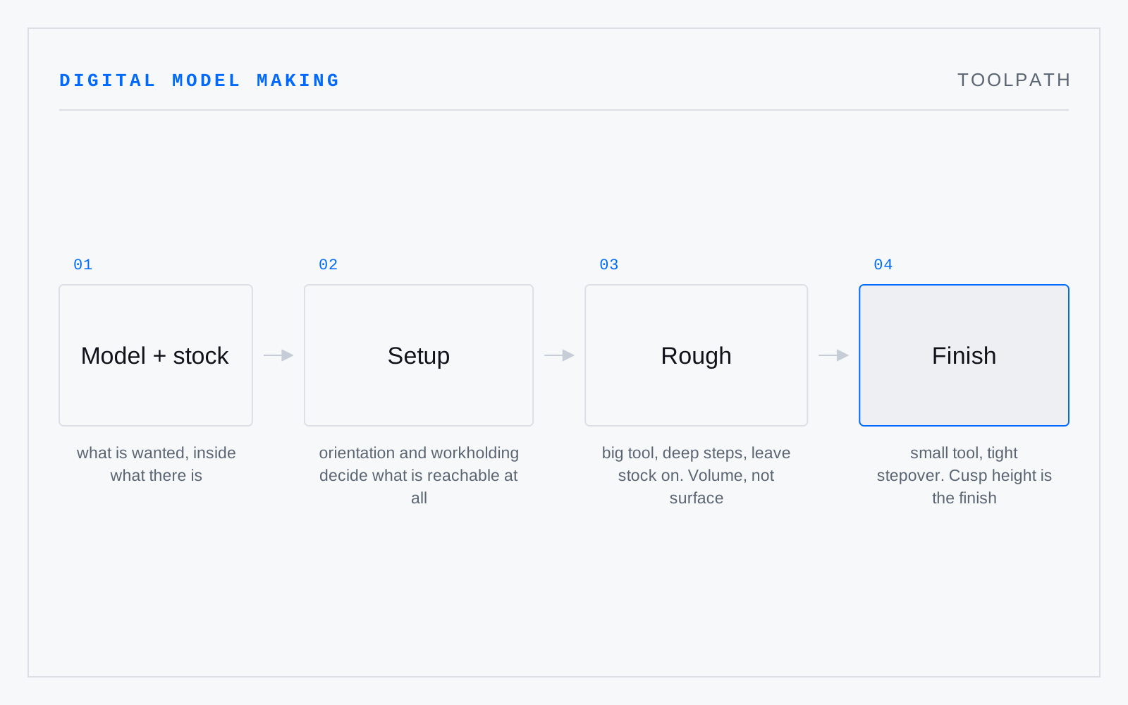
The curve a cutter's centre follows, offset from the wanted surface by the tool's radius and computed by CAM rather than drawn. It carries feed, speed, and depth of cut along with position: roughing clears volume with a large tool, finishing walks the surface with a small one.
In practice
The machine cuts the path, not the model. An internal corner comes out carrying the cutter's radius whether or not the CAD had one, and every unreachable feature is a toolpath problem before it is a design problem.